The evolution of fibre optics has revolutionised data transmission in ways that are critical to high performance and large scale data centres. From indoor and outdoor cabling to stringent Meet-Me-Room (MMR) requirements, each component contributes to an infrastructure that’s robust yet adaptable and meets the demanding standards of Tier 3 and Tier 4 data centres.
Fundamentals of Fibre Optics for Data Centres
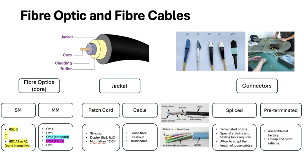
When designing a fibre optic infrastructure for a data centre, the choice of fibre type is critical to meet both performance requirements and space constraints. A common consideration is between single-mode fibre options such as 652.D and 657.A1 or 657.A2. The latters, due to their high bend tolerance, are designed to minimise signal loss in confined spaces where cabling may need to be bent around corners or coiled. This feature is particularly beneficial in data centres where space is often at a premium and maintaining signal integrity in confined layouts is essential.
Another important choice is between multi-mode fibres, which offer flexibility for various high-speed applications over shorter distances. OM3, OM4 and OM5 grades differ in bandwidth capacity and performance. OM3 is designed for 10 Gbps speeds commonly used in data centres, while OM4 and OM5 can support even higher speeds over longer distance, up to 40 Gbps or 100 Gbps, for more data-intensive tasks. OM5 further increases bandwidth by supporting wavelength division multiplexing, which allows multiple signals to be transmitted over a single fibre.
Cable Types for Data Centre
Patch cords are the main components used for cross-conenction. They are available in simplex, duplex and multi-fibre configurations. Simplex cables contain a single fibre, typically used for one-way transmission, while duplex cables contain two fibres, ideal for bi-directional communication. Multi-fibre cables, which typically contain 12 to 24 fibres, enable high-density connectivity, essential for data centres that handle large volumes of data and require space-efficient cabling.
Cables are instead available in loose fibres, breakout and trunk configurations. These three types are central to data centre cabling strategies. Loose fibre cables are designed with individual fibres in a protective tube, which provides flexibility and is often used for outdoor applications or in environments where environmental resistance is essential. Breakout cables contain multiple fibres, each with its own jacket, providing a simple and durable way to connect directly to individual ports without the need for a separate fan-out device. Trunk cables combine multiple fibres within a single jacket, making them ideal for connecting larger areas of the data centre.
Connectors, when to use MPO?
In data centres, where uptime and precision are paramount, choosing the right type of connector affects both performance and ease of maintenance. Two primary types of connectors are used: single fibre connectors and multi fibre connectors.
Single fibre connectors
These include mainly LC, SC and ST connectors, which are used for connections where alignment accuracy and low signal loss are required. These connectors, each housing a single fibre, are often used in lower density applications or where individual fibre connections need to be tightly controlled. For example, LC connectors are popular because of their compact design, which allows for higher density connections in confined spaces.
Multi-fibre connectors
These connectors, such as Multi-Fibre Push-On (MTP/MPO) connectors, allow multiple fibres to be connected simultaneously, supporting high-density environments by consolidating multiple fibres into a single port. MTP/MPO connectors are often used in Meet-Me-Rooms (MMRs) and other high-traffic areas within the data centre, where efficient setup and scalability are critical. By allowing up to 24 fibres to be connected through a single port, these connectors facilitate rapid deployment, reduce cable mass and support flexible network configurations.
Pre-terminated connectors vs On-site splice
Optical fibre cables can be terminated in two ways:
Pre-assembled connectors
These connectors are factory assembled and tested to ensure reliable performance and consistency. Because they are ready to install, pre-terminated connectors reduce the time and cost associated with field termination. This makes them suitable for large-scale deployments, especially in high-density areas of data centres where uptime is critical. However, because these connectors are supplied in fixed lengths, they’re most effective in scenarios with predictable and well-planned cabling layouts.
On-site splice
Unlike pre-terminated options, on-site terminations offer greater flexibility by allowing lengths to be customised directly within the facility. This is particularly beneficial in environments with complex or evolving layouts, where cable runs may need to adapt to physical space constraints. On-site termination requires specialised tools and trained technicians, which can increase initial installation costs, but offers significant adaptability.
Outdoor Cabling Infrastructure
Outdoor cabling presents a substantial problem for data centres in terms of protecting fibres from external stresses such as temperature variations, moisture, and even physical damage. Specific standards for trenching, ducting, and manhole installations ensure that the fibre infrastructure is secure, accessible, and functioning over time.
- Trenching: Outdoor fibre cables are laid within trenches, which are dug to a standard depth of 80 to 100 cm. This depth helps protect the fibre from interference, physical damage, and the risks posed by adjacent utilities. It is also common practice to maintain at least 80 cm of separation from other utility networks to prevent accidental disruptions. The trench itself is layered, often without concrete, to allow for easy adjustments, repairs, and possible expansions.
- Ducting: To further safeguard fibers within the trench, ducts are used to house and protect the cables. Two main types of ducts are typically deployed:
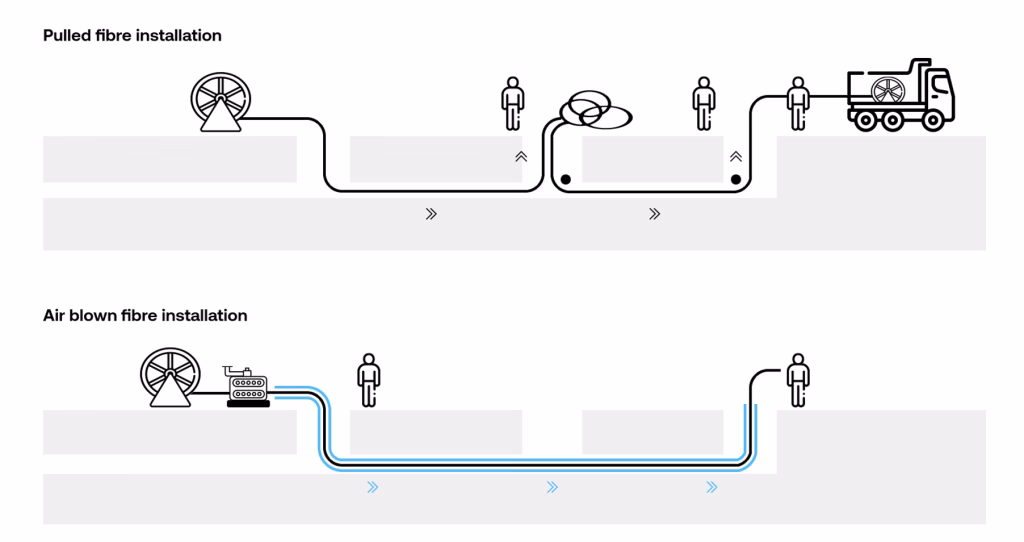
- 160 mm ducts are used for pulling methods, which is a cost-effective but slower deployment technique.
- 40 to 50 mm ducts are reserved for jetting or blowing installations. Jetting enables faster and more scalable deployments, achieving speeds of up to 60 meters per minute. Although this method requires a higher initial investment in equipment, it significantly reduces labor time and allows for future scalability as additional fibers can be blown into place without requiring new trenches.
- Manholes: At regular intervals along the fiber route, manholes are installed to provide access points for cable splicing, deviation, and routine maintenance. Manholes serve as crucial demarcation points, enabling technicians to access and test fibers without disrupting the entire network. They are strategically placed to balance ease of access with protection against environmental exposure, ensuring fibers remain accessible while also safeguarded from moisture and contaminants.
Indoor Cabling Infrastructure and Meet-Me-Room
The Meet-Me-Room (MMR) is a critical connectivity hub in data centres, providing a safe and centralised site for direct hookups between carriers, customers, and data centre networks. As data centres expand to meet increasing connectivity demands, the MMR’s architecture and organisation become vital for efficiency and security, especially in Tier-3 and Tier-4 facilities where uptime and redundancy are critical.
MMR Function and Design
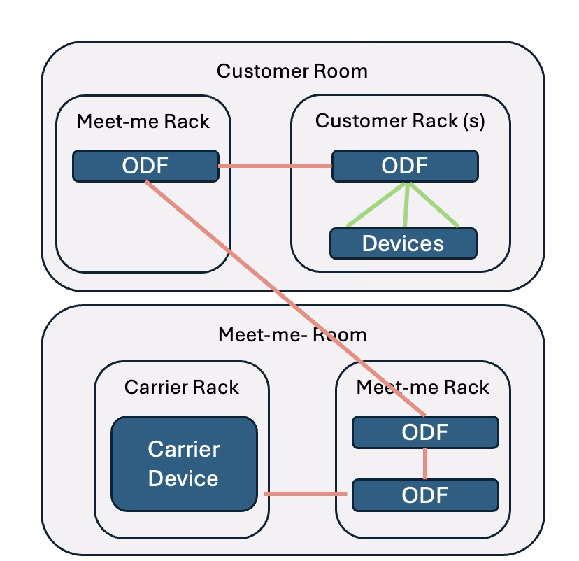
In its most basic form, an MMR serves as a central network hub, consolidating connectivity to facilitate cross-connections between carriers, clients, and data centre operators. This feature not only increases efficiency but also reduces the number of cables running throughout the data centre by consolidating external connections into a single location. With many carriers terminating in the MMR, data centres have flexibility in selecting and managing their providers, resulting in greater network resilience and redundancy.
An MMR typically includes several key components:
- Carrier Racks: These racks house equipment from external carriers, providing a dedicated space for each carrier’s devices.
- Main Distribution Frame (MDF) or Meet-Me-Rack (MMR): A central rack that allows cross-connections between all carriers and customer rooms.
- Cross-Connects: Cross-connects are essential for linking different carriers and customer equipment, supporting a wide range of services and configurations.
- Pre-Cabling: Pre-cabling allows connections between the MMR and customer rooms. To streamline deployments and cross-connection tasks, pre-cabling is often installed on day one. This foresight allows for faster modifications and minimizes disruptions during network upgrades or expansions.
MMR Requirements for Tier-3 and Tier-4 Data Centres
To meet the stringent standards of Tier-3 and Tier-4 data centres, the MMR must adhere to specific design requirements that enhance security, redundancy, and scalability.
- Redundant MMRs for Tier-4: While Tier-3 data centres require one MMR, Tier-4 facilities, which guarantee the highest levels of uptime and fault tolerance, demand two separate MMRs. These rooms must be located in distinct fire protection zones, with entrances at least 20 metres apart to protect against environmental or man-made risks.
- Carrier and Client Separation: For security and organisation, MMR layouts are designed to keep carrier racks and client racks separate. This separation reduces the risk of interference and helps organise the extensive cabling typically required in high-density environments.
- High-Density Hardware: As the primary hub of connectivity, the MMR accommodates a large number of fibres, necessitating high-density hardware. ODFs, cable management trays, and pre-cabled breakout panels allow for effective organization and access. High-density ODFs, in particular, are crucial as they allow data centers to maximize space while providing easy access for maintenance and upgrades.
Fiber Testing Protocols
To ensure peak performance and dependability, data centres must conduct extensive fibre testing processes. These standards ensure that all installed fibres operate at the specified speeds and capacities, without physical or performance concerns like as attenuation, splicing errors, or connection breakage. Testing is also an important stage in quality control, ensuring that supplier materials fulfil specified requirements and providing certification to end customers.
Basic Inspection: Connector Cleaning and Visual Examination
The most fundamental step in fibre testing is basic inspection, which entails inspecting and cleaning connectors to prevent contamination from dust, oil, or other particulates that could interfere with signal transmission. Technicians utilise fibre inspection scopes to evaluate the cleanliness and quality of connectors, looking for scratches, cracks, and other physical flaws that could cause signal loss. Cleaning instruments, such as lint-free wipes and cleaning sticks, are used with the scope to ensure that each connector is clean and operational.
Visual inspections are useful for detecting surface-level pollutants, but they are frequently insufficient for discovering interior abnormalities in the fibre channel. As a result, data centres use more extensive testing techniques to ensure fibre integrity over the whole link.
Tier-1 Testing (Basic Loss, Length, and Polarity Testing)
Tier-1 testing is a basic certification test that measures the fiber’s optical loss, length, and polarity to ensure it meets network standards. By verifying these parameters, Tier-1 testing provides a baseline assessment of the fiber link’s overall performance.
- Loss Measurement: Optical power meters and light sources are used to measure the loss along the fibre path. Loss testing is essential, as even minor attenuation can affect data transmission over long distances, especially in high-density data center environments. The measured loss must fall within acceptable limits to certify that the fibre meets network design specifications.
- Length Measurement: Accurate length measurement is another critical component, as it helps verify that fibers are cut and installed to the correct specifications. Any discrepancies in length could result in unnecessary slack or tension in the fiber, potentially leading to signal loss or damage over time.
- Polarity Testing: Polarity tests verify that signals travel in the correct direction from one end of the fiber link to the other, ensuring proper connectivity throughout the network. This is particularly important for multifiber connections, where maintaining correct polarity across multiple fibers is essential for functional transmission.
Tier-2 Testing (Advanced Splice and Bend Testing with OTDR)
Data centres also use Optical Time Domain Reflectometers (OTDRs) for Tier 2 testing, which provides a more comprehensive examination. This thorough testing pinpoints particular faults throughout the fibre path with great precision. While Tier-2 testing necessitates a larger expenditure in terms of gear and technician training, it yields crucial insights into the fibre’s internal functioning.
- OTDR Testing: OTDRs operate by sending a light pulse through the fibre and measuring the backscatter signal to create a “snapshot” of the fiber link. This data reveals the location and magnitude of any attenuation points—such as splices, connectors, or bends—where signal strength may be compromised.
- Bend Testing: OTDRs are also effective in detecting bends that may be too sharp or improperly configured, which can lead to excessive signal loss. By pinpointing the exact location of such bends, technicians can correct these issues before they impact data center operations.
To know more about optical fibre in data centres, we reached out to Stefano Meroli, PhD in Nuclear Physics and Operations Manager at nLighten, a company known for its innovative data center solutions in Switzerland. Here is his point of view on where he sees the future of fibre infrastructure going in data centres.
“We’re seeing a push toward even higher fiber density and more sophisticated cable management solutions. As demand for data grows, I believe the emphasis will be on integrating new fiber technologies that allow us to transmit more data through the same physical space. Enhanced wavelength-division multiplexing on fibers is just the beginning.