Key takeaways
- At 1 MW, 800 V DC cuts rack current from 18,519 A to 1,250 A, and resistive loss (heat made inside the conductor) falls about 219 times.
- In our worked example, 2 m of copper held to a 0.5% loss weighs 169.1 kg at 54 V and 0.771 kg at 800 V DC, counting resistive heating only.
- Three copper savings are quoted for 800 V DC against 415 V AC (about 40%, 45% and 64%), and each rests on a different basis.
- In Europe, 800 V DC equipment falls, in our reading, under the Low Voltage Directive (75 V to 1,500 V DC), and it is above the 400 V DC limit of the ETSI standard for ICT power interfaces.
- NVIDIA’s first 800 V racks, which its white paper says enter production in the third quarter of 2026, still convert to 54 V inside the compute rack, and its white paper expects moulded-case breakers first.
Feed a 1-megawatt AI rack at 54 volts, the busbar voltage today’s racks use, and it has to draw about 18,500 amps. NVIDIA’s engineers put the copper busbar (a thick copper bar that carries current) needed for that at up to 200 kilograms in a single rack. That is why the industry is moving AI racks to 800 V DC power.
The change reaches beyond the rack. In its May 2025 description, NVIDIA converts 13.8 kV AC grid power to 800 V DC at the edge of the data centre with industrial rectifiers, then distributes DC down the rows. Here 13.8 kV is medium voltage, the level at which utilities supply large sites, and a rectifier is a device that turns AC into DC. NVIDIA’s 2026 white paper gives 34.5 kV as an example for that step and offers several layouts. One is a power rack beside the row. Another is a solid-state transformer, a converter built from power electronics instead of an iron core, which takes medium-voltage AC straight to 800 V DC; NVIDIA expects it toward 2029. But the pressure that started it is an I²R problem (resistive heating, the effect that makes a toaster coil glow), and it bites hardest inside the rack.
The 1 MW wall that broke 54 V DC
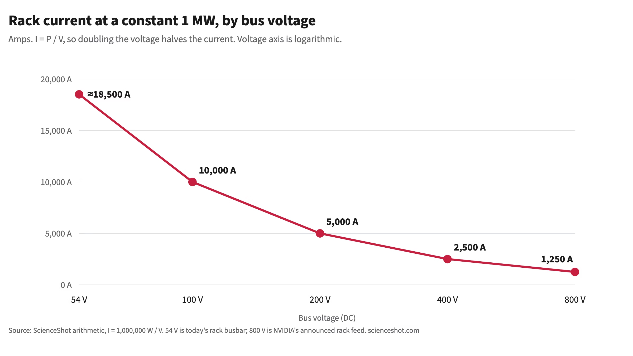
Start with the equation every physics student meets in week one: P = I × V. Power equals current times voltage. Fix the power at 1 megawatt, the rack size NVIDIA is designing its 800 V architecture for, starting in 2027, and current and voltage are locked in an inverse relationship. Push voltage down and current has to go up.
At 54 V, 1 MW means 1,000,000 ÷ 54, about 18,500 amps. NVIDIA puts the busbar copper for that at up to 200 kilograms per rack, and the rack busbars of a 1-gigawatt data centre at up to 200,000 kilograms: 200 tonnes of copper for low-voltage power delivery inside the racks, before a single GPU computes anything.
The reason 54 V fails is simple scaling. At constant power, current goes as 1/V, and the heat a given conductor sheds goes as the square of the current. Holding that heat down at 18,500 amps takes ever more copper cross-section, and a rack runs out of room and weight budget before it runs out of GPUs. The industry hadn’t picked a bad number; the number stopped working at a megawatt.
How far is a 1 MW rack from today’s? ScienceShot’s AI accelerator power dataset lists the NVIDIA B200 at 1,000 W of board power, taken from Lenovo’s product guide. It lists the GB200 NVL72 rack, which holds 72 GPUs, at up to 132 kW. That 132 kW is the design capacity of Vertiv’s reference design for the rack, not a measured draw. NVIDIA’s white paper gives 330 kW per rack for the Vera Rubin NVL72 generation. A 1 MW rack is about 7.6 times the GB200 NVL72 design capacity (our arithmetic).
How much copper 800 V DC actually saves
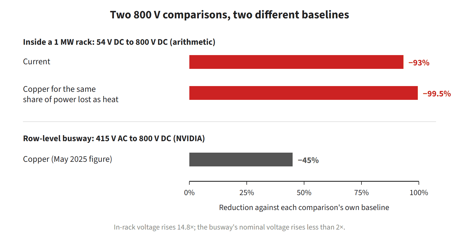
Jump the bus voltage from 54 V to 800 V, a 14.8x step, and at the same 1 MW, current falls to 1,250 amps, 93% less. For a conductor of fixed resistance, the I²R loss falls by 14.8², about 219x. Turn that around and hold the share of power lost as heat constant instead: the conductor’s resistance can then rise 219x, so on paper its cross-section could shrink by about 99.5%.
This is where the most quoted number goes astray. NVIDIA’s figure of 45% less copper does not measure that in-rack step. It compares row-level 800 V DC busways with 415 V AC distribution, a different part of the building and a nominal voltage step of less than 2x. An earlier version of this article set the 45% beside an in-rack prediction and called the difference a gap; the two numbers do not share a baseline. NVIDIA’s own busway figures have also moved. In May 2025 it said 800 V DC carries 85% more power through the same conductor size; in October 2025, that the same wire gauge carries 157% more power than 415 V AC. NVIDIA’s October 2025 white paper gives the basis of the 157% as a fixed wire gauge rated at 48 A continuous. NVIDIA does not publish the calculation behind the 45%.
On its own terms the busway number is plausible. A rough check, our arithmetic, assumes unity power factor and the same current in every conductor of the same size. Three-phase 415 V AC then delivers about 719 watts per amp across three live conductors, roughly 240 W each. 800 V DC delivers 800 W per amp across two, 400 W each. That is about 40% less conductor for the same power, in the same range as NVIDIA’s 45%. NVIDIA also points to DC’s simpler three-wire setup (positive, return and protective earth) against four wires for AC.
Inside the rack, nobody will build a bus with half a percent of today’s copper, because heating is only one constraint. A busbar thin enough to satisfy the heating math would be too flimsy to survive vibration and handling, so there is a minimum mechanical gauge. Insulation and creepage clearances (the minimum distances between live parts) grow with voltage. And conductors are sized for fault current, well above typical load. Ohmic heating math simply doesn’t see those fixed costs, and the tightest constraint sets the bill of materials.
I find this more interesting than “higher voltage, less copper.” CERN’s Large Hadron Collider solves an adjacent version of the problem from the other side: its superconducting main dipole magnets carry 11,080 amps through coils with no resistance, so the coils themselves have no I²R loss (joints, current leads and power converters still dissipate some). One approach lowers I and the other zeroes out R. Data centres can’t superconduct at scale yet (the cryogenics would eat the savings), so they’re doing the only other thing the equation allows: raising V.
The copper problem comes with a separate one, heat removal, covered in our article on liquid cooling for AI racks. NVIDIA’s 2026 white paper plans fully liquid-cooled power shelves, busbars and connectors from its third rack generation. Higher voltage also shortens the conversion chain, but only in NVIDIA’s later native design. In its October 2025 Kyber design, 800 V DC runs to each compute node. There a single 64:1 LLC converter (a resonant converter that divides voltage by a fixed ratio of 64) steps it down to 12 V right next to the GPU. That single stage occupies 26% less area than traditional multi-stage approaches. NVIDIA’s white paper calls this native 800 V distribution inside the rack Gen 4.
The first 800 V racks work differently. NVIDIA says current and near-term systems accept 800 V DC input. They use 800 V to 54 V power shelves, one design with six 15 kW power supplies, so 54 V survives inside the compute rack for now. The same paper lists rack power of up to 145 kW for Gen 1 and 330 kW for Gen 2 (Vera Rubin NVL72). Gen 3 reaches up to 570 kW with liquid-cooled power shelves. For the architecture as a whole, NVIDIA’s May 2025 post claims up to 5% better end-to-end power efficiency than today’s 54 V path. That is a target, and we found no measured result behind it.
A worked example at 1 MW
The table below fixes the geometry and lets the voltage vary. Every conductor is 2 m of copper. Direct current needs two conductors, one out and one back. Three-phase AC needs three live conductors, and the table counts only those. Two questions get answered. How much power does a 1,000 mm² conductor waste as heat? And how much copper is needed if the loss must stay at 0.5% of the load, which is 5 kW?
| System carrying 1 MW | Current | Loss in 2 m of 1,000 mm² copper | Share of 1 MW | Section per conductor for 0.5% loss | Copper mass at that section |
|---|---|---|---|---|---|
| 54 V DC, two conductors | 18,519 A | 23.65 kW | 2.365% | 4,730 mm² | 169.1 kg |
| 400 V DC, two conductors | 2,500 A | 431 W | 0.0431% | 86.2 mm² | 3.08 kg |
| 800 V DC two conductors, or ±400 V balanced (800 V pole to pole) | 1,250 A | 107.8 W | 0.0108% | 21.55 mm² | 0.771 kg |
| 415 V AC three-phase, power factor 1, three conductors | 1,391 A per phase | 200.2 W | 0.0200% | 40.04 mm² | 2.15 kg |
At 54 V the 1,000 mm² pair loses 23.65 kW, which is 2.365% of the load. Holding the loss to 0.5% takes 4,730 mm² per conductor and 169.1 kg of copper. That is the same order of magnitude as NVIDIA’s up to 200 kg, although NVIDIA does not publish its geometry or its loss limit. At 800 V DC the same target takes 21.55 mm² and 0.771 kg. Against 400 V DC, the 800 V DC set needs one quarter of the copper at an equal loss share: 0.771 kg against 3.08 kg.
The last two rows show where a third copper figure comes from. Hold the share of power lost as heat equal in both systems, and count only the live conductors. Then 800 V DC needs 0.771 kg where 415 V AC needs 2.15 kg. The ratio is 0.359, so about 64% less copper. This is our equal-loss figure, with ideal geometry and a balanced load.
Three percentages therefore circulate for 800 V DC against 415 V AC, and each has its own basis. About 40% is the equal-current figure from the section above: the same current in every conductor of the same size. The 45% is NVIDIA’s, for row-level busways, with a calculation NVIDIA does not publish. The 64% is the equal-loss figure from the table. They answer different questions, so quote the basis with the number and never compare one against another.
Temperature moves the results. The International Electrotechnical Commission specifies a temperature coefficient of 0.00393 per degree Celsius for standard copper at 20 °C. Resistance therefore rises about 0.393% per degree. At 70 °C the 54 V loss in the 1,000 mm² pair becomes 28.30 kW. The section for a 0.5% loss grows to 5,660 mm² at 54 V and to 25.8 mm² at 800 V DC.
The table also flatters the high-voltage rows. A section of 21.55 mm² carrying 1,250 A is a current density of 58 A/mm². The loss target allows that. The temperature-rise limit and the fault-current rating, which the table leaves out, will set the real section.
±400 V and the OCP Diablo 400 specification
An 800 V rack does not have to mean one positive conductor and one return. The Open Compute Project (OCP, an industry group that publishes open data centre hardware designs) splits the 800 V into two poles of ±400 V. A midpoint called common sits between them. Measured from either pole to common the voltage is 400 V. Measured from one pole to the other it is 800 V.
The specification is Diablo 400: Rack and Power, written by Microsoft, Meta and Google. Its status is a base specification at version 0.7.0, effective 1 March 2026. Version 0.5.0 was the first release, on 5 May 2025. We found no evidence that it has been ratified, and it is not a final 1.0.
The nominal voltage is ±400 V DC: 410 V at no load and 400 V at full load, with a tolerance of ±0.5%. The rack busbar has three conductors (+400 V, -400 V and common) and is designed for up to 1.1 MW of average load. Output cables run from 63 A (50 kW) to 125 A (100 kW) each, with a voltage-drop budget of 0.1% over 5 m. A two-wire option delivers 800 V DC at the power shelf output. The rack power target runs from 800 kW to 1 MW or more, with the option to put power racks in parallel. The DC load depends on the AC input: 800 kW to 1.1 MW at 480 V AC, up to 1.1 MW at 415 V AC and up to 718 kW at 400 V AC.
In the table above, the ±400 V row counts the two outer conductors of a balanced system. Each pole carries 1,250 A, and the common conductor carries close to zero when the two poles share the load equally. The OCP said in August 2025 that it picked 400 V to reuse the supply chain built for electric vehicles. In its August 2026 post, the OCP says a Mt Diablo 2.0 for native 800 V is coming later, without a date.
NVIDIA made a different choice. It uses a single-ended 800 V DC configuration, meaning one positive and one return conductor with no midpoint. Its October 2025 white paper gives the reason as protection device availability and system simplicity. Bipolar configurations such as ±400 V need specialised three-pole breakers, it says, and those are not widely available. NVIDIA also designs its IT rack to accept sources with an 800 V total potential under several grounding schemes, so ±400 V equipment can power it.
Get the next one by email
Power, cooling, chips and the rules that shape them. No spam, unsubscribe any time.
What 800 V DC means in Europe
The main EU product-safety law for this equipment is Directive 2014/35/EU, the Low Voltage Directive (LVD). It applies to electrical equipment designed for a voltage rating between 50 and 1,000 V for alternating current. For direct current the range is 75 to 1,500 V. Annex II lists exclusions, and none of them is generic data centre power equipment. 800 V DC is inside the range, and so are 400 V DC and ±400 V. The Commission’s LVD page says the general product safety directive covers consumer goods below 75 V DC. A 54 V DC rack is below the LVD’s range.
Power shelves, rectifiers, DC/DC converters, breakers, busways and connectors designed for these voltages and sold in the EU are in scope. Their manufacturer must assess conformity against the safety objectives in Annex I and keep technical documentation for 10 years. It must also issue an EU declaration of conformity and apply the CE marking. The conformity route in Annex III is internal production control (Module A), which the manufacturer carries out itself. One Annex I objective is that temperatures, arcs or radiation that would cause danger are not produced. Equipment built to harmonised standards, whose references are published in the EU’s Official Journal, is presumed to conform (a legal assumption that the product meets the objectives). Where no harmonised standard exists, Article 13 opens the same presumption to IEC standards after a publication procedure, and Article 14 to national standards. This is our reading of the Directive, not legal advice.
The LVD regulates equipment placed on the market. It does not write installation rules for a data hall. National rules do. The OCP white paper says most countries outside the United States base them on IEC 60364, which applies up to 1,000 V AC or 1,500 V DC. We did not read IEC 60364 or any national code, and we did not check whether other EU product laws also apply.
ETSI EN 300 132-3, version 2.3.1 of January 2023, is the European standard for the power interface at the input of information and communication technology (ICT) equipment. Its title says up to 400 V DC. Its scope names telecom centres, radio base stations, data centres and customer premises. Normal service is 260 to 400 V DC, and 400 to 410 V is allowed for 1 s as an abnormal condition. A 400 V DC system fits the standard. An 800 V DC system does not. Basic safety is outside its scope, and a note refers to EN 62368-1 for equipment rated up to 600 V.
EN 62368-1 and IEC 62368-1 are the main product-safety standards for ICT equipment, and as ETSI cites them they stop at 600 V. The OCP white paper also reports that interpretive guidance has been requested from the IEC committee on whether the existing 600 V scope permits 850 V DC. The same paper reports that technical committee 108 of the IEC has an ad hoc group. The group is drafting a proposal to extend the scope to 1,000 V AC and 1,500 V DC, and a preliminary report was expected in the second quarter of 2026. We found no outcome. NVIDIA states that its initial Power Rack applies existing IT equipment certification methods under UL 62368-1 (the North American edition of the standard). It says the rack limits data-hall exposure to 800 V DC and can be certified now for UL and IEC regions. That is NVIDIA’s statement, and we have not seen a certificate.
The list of standard nominal voltages, IEC 60038, is being amended for low-voltage DC. The OCP white paper quotes the draft values as 175/350 V, 350 V, 350/700 V, 700 V, 700/1,400 V and 1,400 V. It notes that a 400 V and 800 V series would reach 1,600 V, above the 1,500 V limit. We did not open IEC 60038. In the pending list, the nearest value to 800 V is 700 V.
The Open Direct Current Alliance (ODCA), a German industry alliance, uses a 700 V nominal band for industrial DC. It is a working party of the ZVEI electrical industry association. On 23 April 2026 it updated its system description for DC microgrids, aligning the nominal voltage to 700 V DC for industrial systems, in line with the soon-to-be published IEC standard. VDE SPEC 90037, version 1.1 of 6 July 2026, describes industrial DC grids with a 700 V nominal band and a 540 V band. It states that it need not be compatible with grids for in-building systems or data centres.
The research behind this page found no European Standard, ETSI document or IEC standard that sets an 800 V DC power interface for ICT equipment. We cannot rule out a draft that we did not find. The OCP white paper counts more than 70 product-level standards relevant to an 800 V DC architecture. The majority already address 800 V DC, and a subset need updating or new standards. The paper adds that most products in those categories have not yet been vetted or tested for 800 V or 1,500 V DC in data centres. Our reading for a European operator: 800 V DC products need CE marking under the LVD. There is no European interface standard to cite, so a specification today rests on vendor and OCP documents.
Protection: why DC is harder to switch off
Alternating current passes through zero at every half cycle, and the arc that forms when a breaker opens goes out naturally at that moment. ABB’s training module on direct current says that this zero crossing does not occur with direct current, which makes interruption far more critical. NVIDIA’s white paper gives the same physics in its table of fault behaviours. DC fault current is continuous with no zero-crossing. A series arc (an arc across a break within one conductor) can sustain itself and is harder to extinguish.
To break a DC short circuit, ABB explains, the breaker has to create an arc voltage higher than the supply voltage, which forces the current to zero. Low-voltage breakers do it by connecting poles (contacts) in series, with 3 or 4 arc chambers. The OCP white paper adds that most DC breakers on the market use series poles and a thermal-magnetic trip unit, which opens the breaker through a heat element and a magnet. Short-circuit breaking time runs from about 1 ms for small miniature circuit breakers to a few tens of milliseconds for power circuit breakers. Fast fuses for semiconductor protection clear in under 1 ms to several ms.
Speed matters because of the capacitors in DC equipment. When a fault discharges those capacitors, the same paper says, protection may have only a few hundred microseconds to act, so fast-acting overcurrent protection is required. It also states that no standard or recognised practice exists for assessing the short-circuit current of these DC systems. IEC technical committee 73 has recently started a project to fill the gap. UL standards for branch-circuit fuses (the fuses that protect each outgoing circuit) are currently limited to 600 V.
Solid-state circuit breakers (SSCBs) detect faults electronically and cut the current before the fault reaches its peak. NVIDIA’s white paper says conventional devices may let fault current keep rising for several milliseconds, while SSCBs can isolate faults within a millisecond. Even so, NVIDIA expects moulded-case circuit breakers (MCCBs, mechanical breakers in a sealed plastic housing) to be the primary branch protection device in initial production systems. It calls SSCB technology mature at lower current ratings. Wider deployment, it says, depends on how ready the supply chain is, on regulatory certification, on product availability and on cost. Its first SSCB targets are 125 A air-cooled units for the 800 V to 54 V power shelves. For future native 800 V compute racks it targets 1,250 A units, likely liquid-cooled.
Series arcs generally do not draw enough current to trip conventional protection, so NVIDIA says they need dedicated arc fault detection. On shock, its table says AC can cause a muscle lock-on effect and DC often causes a single muscle contraction, and that both need strict personnel protection. NVIDIA’s 125 A DC power whips (flexible cables that feed the rack) are protected by a normally open contactor. It closes only after the connector is mechanically locked. The Diablo 400 connector uses short pins to prevent arcing.
Grounding is still open. NVIDIA lists high-resistance midpoint, high-resistance return, floating and solid grounding as options under evaluation and says system-level studies will decide. The OCP white paper says more research is needed on arc flash behaviour in DC systems. An arc flash is a violent electrical arc that releases heat and light. The industry still needs agreed methods to calculate incident energy and arc-flash boundaries. The OCP also says it is working with UL Solutions, NFPA, IEEE and IEC on the safety certifications and regulatory frameworks that global deployment needs.
Who’s actually building 800 V DC hardware
The hardware is arriving before the standards are final. At the Open Compute Project, the community published its low-voltage DC distribution white paper (version 1.0, 30 March 2026, 155 pages). A work group led by ABB, Eaton, Siemens, Google, Schneider Electric, UL Solutions and DC Opportunities wrote it, with contributors including NVIDIA and Microsoft. NVIDIA’s August 2026 blog calls it a joint white paper with Google and Microsoft, and the OCP’s own post on the work names the same three companies. The OCP’s solid-state transformer specification, written by Google, Microsoft and NVIDIA, is revision 0.3.0, marked first draft and effective 22 June 2026. It describes an 800 V DC unipolar output with a static tolerance of ±1%.
NVIDIA’s MGX-compatible 800 V DC power rack (MGX is its modular rack design) is due in the second half of 2026. It is designed to slot into facilities already wired for AC. NVIDIA’s white paper puts it into production in the third quarter of 2026, at about 660 kW per power rack. We found no shipment notice. The bigger step is Kyber, NVIDIA’s rack-scale system for Rubin Ultra GPUs. NVIDIA says full-scale production of 800 V DC data centres will coincide with Kyber systems in 2027. Its May 2025 post says it showed an 800 V sidecar (a separate cabinet that supplies a rack’s power) for 576 Rubin Ultra GPUs in a single Kyber rack at GTC 2025. NVIDIA’s own target once 800 V DC runs at scale is up to a 30% reduction in total cost of ownership, meaning all costs over the system’s life. That is a target from the May 2025 post, and NVIDIA’s white paper lists a cost, reliability and lifecycle study as future work.
Suppliers have dated their own plans. On 20 October 2025 Vertiv said its 800 V DC power portfolio is planned for the second half of 2026, to support the 2027 rollout of NVIDIA Rubin Ultra platforms. It was still finalising component specifications. On 16 October 2025 Schneider Electric wrote that its 800 V DC sidecar will be in the market well before Rubin Ultra. It says the Kyber racks begin shipping in 2027. On 13 October 2025 Infineon announced hot-swap technology (replacing a board without powering down) for 800 V server boards. On 2 June 2026 it added a 30 kW three-phase power factor correction evaluation board with peak efficiency above 99 percent, available for evaluation soon.
On the component side, STMicroelectronics wrote on 13 October 2025 that NVIDIA had validated its 12 kW power delivery board for production testing. On 17 March 2026 it wrote that ST and NVIDIA would present a 6 kW and a 20 kW board. The 20 kW board steps 800 V to 6 V at a peak efficiency of 96.5%. In a release dated 21 September 2026, ABB introduced its Infinitus DC portfolio, built around a solid-state transformer that converts medium-voltage AC to 800 V DC. ABB says the first DC-native facilities using the full portfolio should be operating within two to three years. It estimates that 25 to 40% of new capacity installed in 2030 could use DC distribution, and it calls its solid-state breaker the first fully IEC-certified one. These are the companies’ statements, and we have not verified any of them in the field.
⚡ PHOTON’S TAKE
Before you believe any copper-savings number, ask what it is compared against. 54V to 800V inside a rack and 415V AC to 800V DC along a row are different steps, and their percentages cannot be subtracted from each other. The physics says the in-rack saving is huge on paper; clearances, mechanical gauge and fault current decide how much of it survives into the bill of materials. That is the number worth asking your vendor for.
What comes after 800 V
The next three years are the ones to watch. NVIDIA’s white paper has the Power Rack entering production in the third quarter of 2026. A row-level power center, adjustable up to 2 MW of output, follows as soon as the third quarter of 2027. Direct conversion from medium voltage to 800 V DC with a solid-state transformer is expected toward 2029. NVIDIA’s May 2025 post says Kyber arrives in 2027. On the standards side, drafts already exist. Diablo 400 is at version 0.7.0, the low-voltage DC white paper at version 1.0 and the solid-state transformer specification at version 0.3. A native 800 V Mt Diablo 2.0 has no date.
NVIDIA’s white paper says 800 V DC is not intended to replace existing 415 and 480 V AC systems but to complement them and coexist alongside them. It calls 800 V DC the highest voltage level that can be broadly adopted at the rack. Its October 2025 white paper lists 1,500 V DC as a potential long-term target. If NVIDIA’s claimed 30% TCO reduction holds up in production, 800 V will become the default assumption for anyone building a gigawatt-class AI campus. This generation already assumes the grid, not the GPU, is the real bottleneck.
I expect 800 V to be a way station. The I²R pressure that killed 54 V still applies at 800 V; the ceiling has only moved further out. Whatever comes after this generation of racks, higher DC voltages still or new conductor materials, will be decided by the same equation: P equals I times V, and something in that relationship always has to give.
Sources
- NVIDIA Technical Blog, 20 May 2025, NVIDIA 800 VDC Architecture Will Power the Next Generation of AI Factories
- NVIDIA Technical Blog, 13 October 2025, Building the 800 VDC Ecosystem for Efficient, Scalable AI Factories
- NVIDIA white paper, 800 VDC Architecture for Next-Generation AI Infrastructure, October 2025
- NVIDIA white paper, 800 VDC Architecture: Industry Alignment and Execution, 2026
- NVIDIA Blog, 11 August 2026, Why Scaling AI Compute Performance Requires a New Power Architecture
- Open Compute Project, Diablo 400 Project: Rack and Power 0.7.0 Base Specification, effective 1 March 2026
- Open Compute Project, Data Center Facility, Low Voltage Direct Current Power Distribution, version 1.0, 30 March 2026
- Open Compute Project blog, 5 August 2025, Major contributions advance OCP Open Systems for AI at APAC Summit
- Open Compute Project blog, 11 August 2026, Powering the Next Era of AI
- Directive 2014/35/EU (Low Voltage Directive), Official Journal L 96, 29 March 2014
- European Commission, Low Voltage Directive
- ETSI EN 300 132-3 V2.3.1 (2023-01), power supply interface at the input of ICT equipment, up to 400 V DC
- Open Direct Current Alliance (ZVEI), update of the system description for DC microgrids, 23 April 2026
- ABB Electrification Academy, Introduction to Direct Current Applications
- ABB press release on the Infinitus DC portfolio, dated 21 September 2026
- Vertiv, 20 October 2025, collaboration with NVIDIA on 800 VDC platform designs
- Schneider Electric blog, 16 October 2025, The 1 MW AI IT rack is coming, and it needs 800 VDC power
- Infineon press release, 13 October 2025 and Infineon market news, 2 June 2026
- STMicroelectronics blog, 800 V HVDC for AI data centers, updated through 29 June 2026
- US National Bureau of Standards, Handbook 100, Copper Wire Tables, 1966 and Copper Development Association, copper properties
- Open Compute Project, Solid State Transformer design specification, revision 0.3.0, effective 22 June 2026
- VDE SPEC 90037 V1.1, 6 July 2026 (VDE SPEC publications)
- CERN, Pulling together: superconducting electromagnets
- ScienceShot, AI accelerator power dataset
Correction, 26 September 2026: an earlier version compared NVIDIA’s 45% copper figure, which is measured against 415V AC busways, with an in-rack 54V calculation, and presented the difference as a gap. It also attributed copper and operating-cost figures to Converge Digest that we could not find in its reporting; they have been removed.
Correction, 10 October 2026: this article was checked against NVIDIA’s and the Open Compute Project’s own documents and these statements were corrected. It said NVIDIA converts 13.8 kV AC grid power to 800 V DC at the edge of the data centre. That is the figure in NVIDIA’s May 2025 post; its 2026 white paper gives 34.5 kV as an example. It credited the March 2026 Open Compute Project white paper to NVIDIA, Google and Microsoft. The paper is a community document written by a work group led by ABB, Eaton, Siemens, Google, Schneider Electric, UL Solutions and DC Opportunities, with NVIDIA and Microsoft among the contributors. It dated the solid-state transformer draft to July 2026. The document is revision 0.3.0, effective 22 June 2026. It gave Kyber’s timing as the second half of 2027, citing a report we could not verify. NVIDIA says 2027. It presented the 64:1 converter that steps 800 V down to 12 V at each node as the design of 800 V racks in general. That belongs to NVIDIA’s later native design, and the first 800 V racks still convert to 54 V inside the compute rack. It gave the 5% efficiency figure right after a reference to the October 2025 post and the 30% cost figure without a source. Both come from the May 2025 post and are NVIDIA targets. It said STMicroelectronics presented two boards in March 2026, while ST’s post says it would present them. It described the Open Compute Project’s shared DC specifications as arriving in 2027, when drafts were already published in 2026. The same update added the worked table and the sections on ±400 V, Europe and protection.
Cite this article
Major, A. (2026, September 9). 800V DC Power for 1 MW Server Racks: Copper, Safety, EU Rules. ScienceShot. https://scienceshot.com/post/800v-dc-power-ai-racks
Major, Albert. “800V DC Power for 1 MW Server Racks: Copper, Safety, EU Rules.” ScienceShot, 9 Sept. 2026, scienceshot.com/post/800v-dc-power-ai-racks.
Major, Albert. “800V DC Power for 1 MW Server Racks: Copper, Safety, EU Rules.” ScienceShot, September 9, 2026. https://scienceshot.com/post/800v-dc-power-ai-racks.
@online{scienceshot-800v-dc-power-ai-2026,
  author       = {Major, Albert},
  title        = {{800V DC Power for 1 MW Server Racks: Copper, Safety, EU Rules}},
  organization = {ScienceShot},
  date         = {2026-09-09},
  year         = {2026},
  url          = {https://scienceshot.com/post/800v-dc-power-ai-racks}
}
https://scienceshot.com/post/800v-dc-power-ai-racks
Get the weekly brief
Sourced analysis of data-centre engineering and regulation, every Monday. No spam, unsubscribe any time.